 |
 |
 |
|
Electronic Design Process (pre-2001) |
||||||||
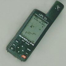 Global Positioning System receiver |
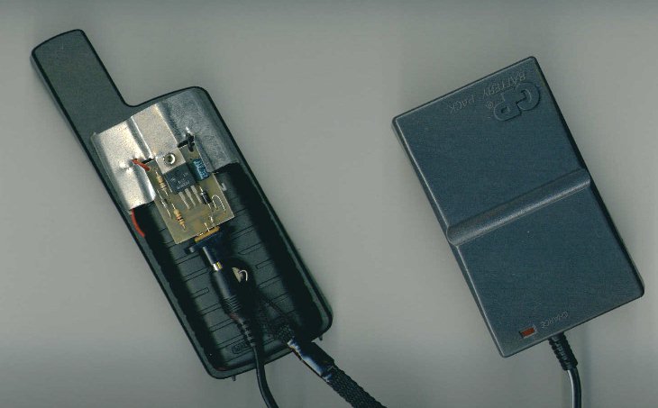
The Problem:This GPS receiver is powered by 2 AA batteries. They are only strong enough for the GPS to stay on for about two hours, and this seems like quite a waste. I would like to be able to use a larger battery, and sometimes even an AC adapter.The Solution:Make a small circuit board that sends a constant 3 volts into the battery compartment, and that is powered by any low DC voltage. It will be mechanically compact, even including a heat sink. |
|
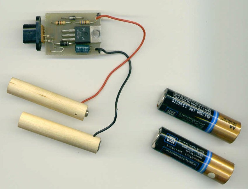
The circuit board is finished, after several hours of tracing, etching, and soldering. These wooden dowels fit into place like batteries. |
 |
|
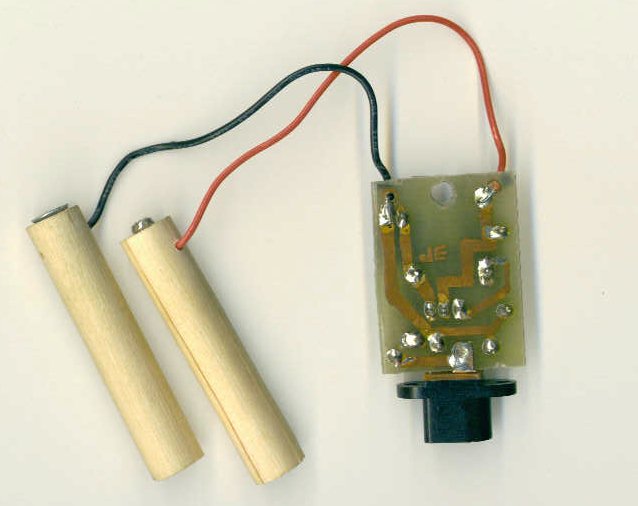
This is the bottom side of the circuit board. You can see the thin traces of copper, and the beads of solder connecting each pin of each component. |
 |
|
The circuit board is very thin and sturdy, so I didn't need to seal it inside its own protective box. However, I did fashion a heat sink that cools down the voltage regulator. |
 |
| It works! | 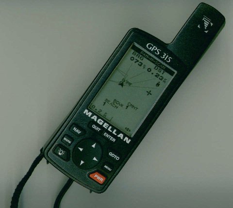 |
The finished product is a digital audio recorder. I apologize for the messiness; I was 15 years old at the time.
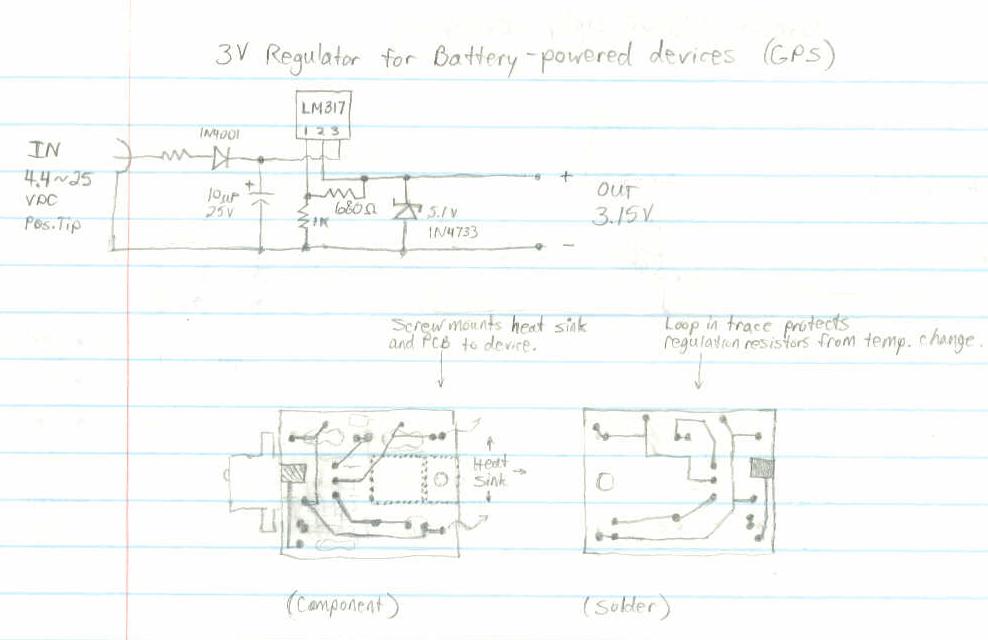
Schematic diagram: Page 1 of 2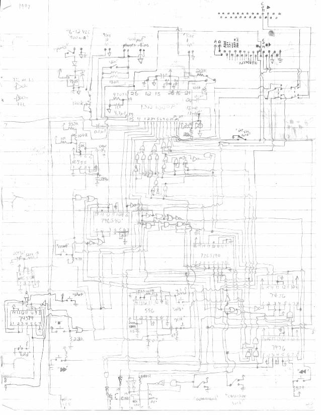
| PCB #1: Component view. | 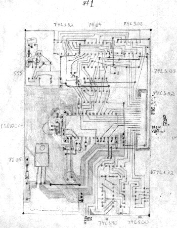 |
| PCB #1: Copper trace & solder view. | 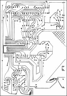 |